TIG Pre Flow and Post Flow: Factory Setup and QC Guide
Introduction
TIG pre flow and post flow control when shielding gas reaches the work before an arc starts and how long it continues after the arc ends. They are time settings, not substitutes for the correct gas flow rate. For a production team, the useful question is whether the complete start-and-stop sequence protects the intended joint and can be repeated across operators, shifts and machines.
This guide helps factory engineers, OEM equipment buyers and quality teams build a documented timing trial. It separates display settings from observed events, explains what a supplier demonstration should record and provides a simple gas-use calculation. Final settings and acceptance remain governed by the specific equipment instructions, approved welding procedure and responsible welding engineer. The examples are planning aids, not tested GWELD parameters or universal welding prescriptions.
What Do TIG Pre Flow and Post Flow Mean?
TIG pre flow is the gas-delivery interval before arc initiation. TIG post flow is the gas-delivery interval after arc termination. Keeping the torch in the intended position matters during the latter interval. A longer timer does not protect the weld if the torch is moved away before coverage is complete.
Keep duration separate from flow rate
Record time in seconds and flow rate in the units actually used by the instrument. A control labelled post flow does not specify litres per minute, and a regulator reading does not establish how long the valve remains open. Put both values on the setup record so engineering and purchasing do not compare unlike quantities.
For gas choice, units and the wider shielding arrangement, use the GWELD TIG welding gas and flow-rate guide. This article focuses on timing and verification, rather than repeating that guide's conversion chart.
The Miller control manual identifies preflow and postflow as different portions of the welding sequence. Its settings belong to the stated equipment, not automatically to another brand or model.
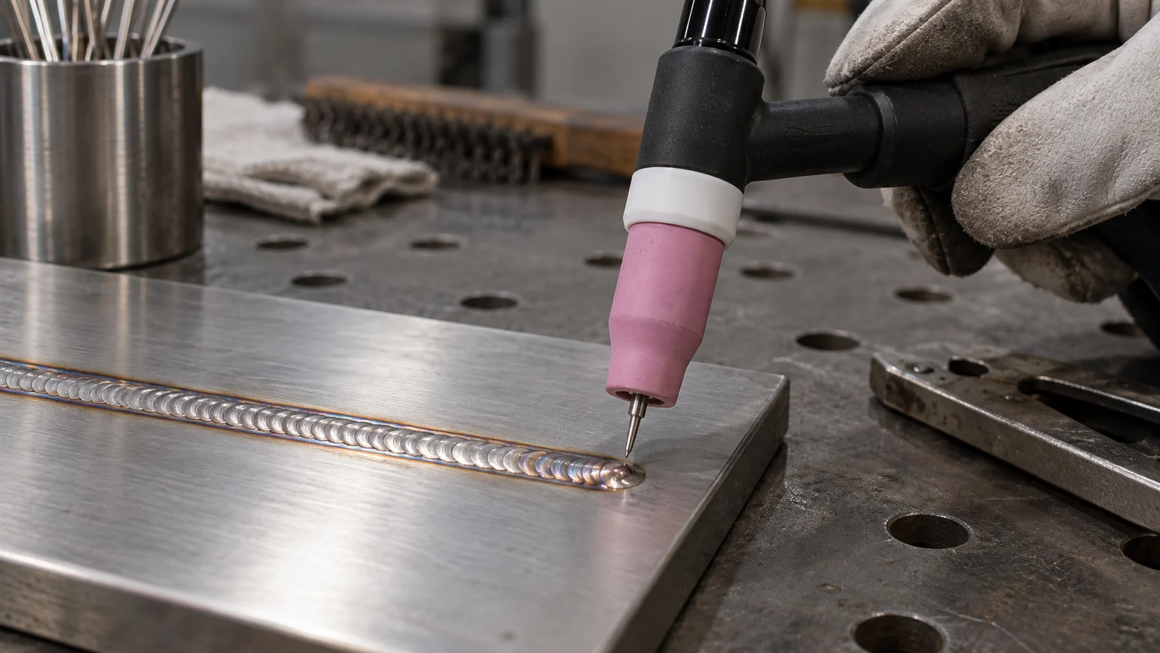
AI-generated illustration of a torch held at a weld end; not a measured timing or acceptance result.
Map the Actual Start and Stop Sequence
Create a short event record for the selected operating mode before evaluating a timer. Note what the operator commands, what the gas system does and when the arc actually begins or ends. This separates a panel value from an observed machine sequence and helps distinguish gas timing from current ramps.
Use an event map rather than a panel photograph
| Event to record | Evidence needed for the trial |
|---|---|
| Start command and gas delivery | Selected mode, command source and observed start sequence |
| Arc initiation and welding | Sample identity, procedure and relevant operating controls |
| Arc termination | Stop command, current ramp and actual arc-end event |
| Post-flow completion | Torch position, valve stop and recorded observations |
Ask the supplier whether automatic timing, trigger mode, remote control or a repeated-start function changes this sequence. Do not assume that two machines with the same displayed number behave identically. The Lincoln Aspect 230 operator manual illustrates model-specific sequencing and an automatic post-flow option; check the manual for the actual machine being purchased.
Make a separate record when the operating mode changes. A clear description of the command and arc-end events is more useful than an unexplained video showing only a countdown. Do not access live electrical components to obtain timing evidence.
Why There Is No Universal Post-Flow Setting
A generic TIG post flow time rule is not a qualification result. Treat published examples as context, then use the selected model's instructions and a representative approved trial. Record the reason for the chosen setting rather than presenting a single number as suitable for every material, torch and production cycle.
Ask what a recommendation actually covers
A technical article may describe a useful rule of thumb, while an equipment manual may specify a default, a range or an automatic function. Those are different kinds of information. None establishes acceptance for a particular customer's joint without the required procedure and inspection.
Miller's shielding-gas guidance discusses both timing and keeping coverage over the completed weld. Use that discussion to identify checks, not to claim that GWELD has validated one fixed timing value for all applications.
Document the selected alloy, joint, welding conditions, torch arrangement and acceptance criteria beside the timing decision. If a supplier cannot state the source or conditions behind a recommendation, keep that item open in the purchasing review. Increasing time alone is not evidence that an underlying delivery fault has been corrected.
Check the Gas Path Before Changing Timers
Confirm the basic installation against the equipment and gas-system instructions before comparing timer values. A timing trial should not quietly become a test of different hoses, loose fittings or damaged consumables. Record the starting configuration so an accepted result can be reproduced.
Freeze the hardware configuration
- Identify the gas specification, regulator or flowmeter and its units.
- Record hose routing, connection arrangement and torch identification.
- Confirm the cup, collet or gas lens, tungsten and applicable consumable fit.
- Record the approved flow check method and result with gas running.
- Note environmental conditions and the relevant extraction arrangement.
Have trained personnel inspect and service the installation using approved methods. Follow isolation instructions before making connections or replacing parts. Do not loosen pressurized fittings, defeat safety devices or obstruct required ventilation to imitate a better shielding condition.
Do not use the timer to hide another change
If the trial replaces a torch or changes the gas path, record that as a configuration change. Restore the agreed baseline or plan a separate comparison. A longer pre-flow may appear to improve a start, but that observation does not identify which component caused the original problem.
The gas lens fit and procurement guide can support the consumable review. It does not replace the model-specific connection instructions or the customer's approved welding procedure.
Run a Controlled Pre-Flow and Post-Flow Trial
Use identified representative samples and a written trial plan. Change one authorized variable at a time, keep the remaining setup documented and link each result to the exact configuration. The purpose is to select a repeatable sequence, not to find the shortest possible timer at any cost.
Agree the trial before the demonstration
- Identify the drawing, material, joint, procedure and inspection requirements.
- Save the baseline machine mode, gas arrangement and control values.
- Define the single timing change and the evidence needed to evaluate it.
- Run the agreed sample using trained personnel and required protection.
- Record start, termination, torch-hold and inspection observations.
- Approve, reject or investigate the change with the responsible team.
Include the production events that matter: an initial start, a stop at the intended joint location and any approved restart sequence. Decide in advance whether additional samples or inspection are required. Do not infer reliable production behaviour from one attractive demonstration bead.
Keep observation separate from approval
A video can help document torch movement and event order, but it is not a substitute for the specified weld examination. Record who observed the sequence and who accepted the sample. If conditions differ from the trial plan, describe the deviation instead of silently treating the result as directly comparable.
Retain rejected and inconclusive trial records too. They explain why a value was not adopted and prevent the same unsupported shortcut from being reintroduced when a machine or operator changes.
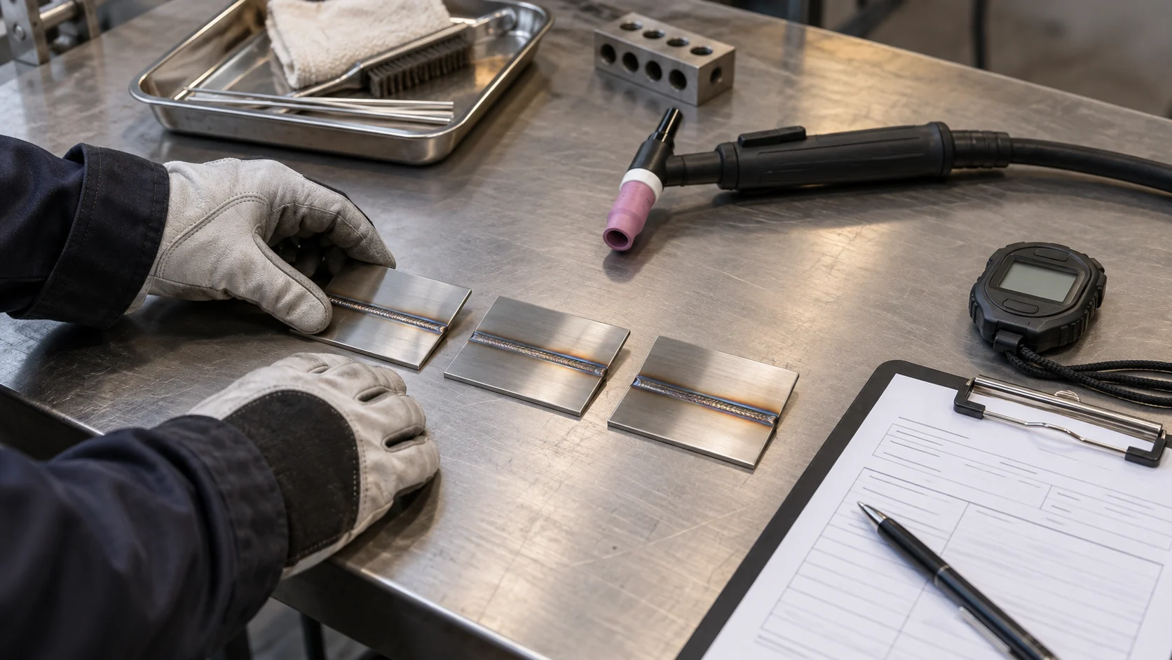
AI-generated illustration of documenting trial samples; no displayed readings or completed test results.
Investigate Start and Stop Symptoms Systematically
Use the location and timing of a symptom to organize the investigation, not to diagnose the cause automatically. Record whether it appeared at the first start, during welding, at termination or on the following start. More than one variable may need professional evaluation.
Describe the event before proposing a cure
For an inconsistent start, note the operating mode, command sequence, sample preparation and observed gas-delivery sequence. For a termination concern, record the arc-end event, torch position and hold behaviour. Keep visual observations distinct from any inspection finding or acceptance decision.
If the tungsten changes appearance, document its condition before and after the trial and follow the approved electrode preparation process. Our TIG tungsten contamination guide covers a separate diagnostic topic. Do not assume that extending post-flow repairs an already contaminated electrode.
Keep the defect investigation traceable
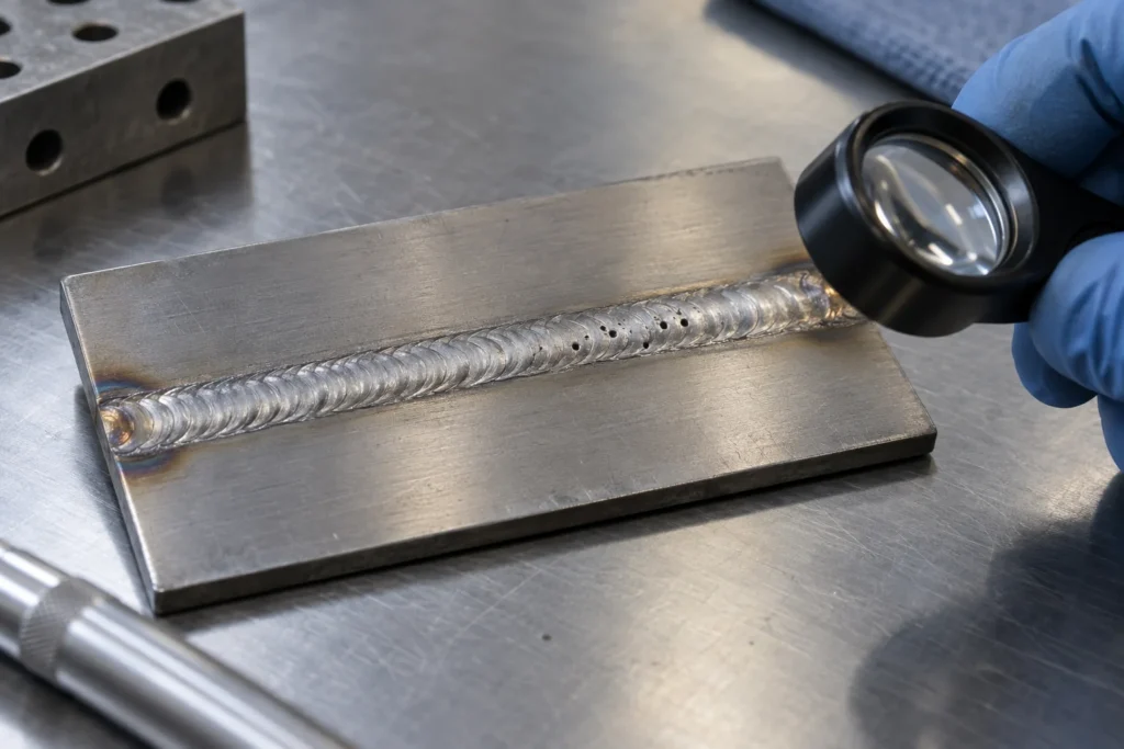
When porosity is reported, link the report to the sample, examination method and complete setup rather than treating it as proof of one timer fault. Use the TIG welding porosity troubleshooting guide for the broader investigation. Escalate persistent defects or unexpected machine behaviour to qualified welding or service personnel.
Avoid running a sequence of undocumented adjustments until a sample looks better. Without a controlled baseline, the team cannot explain the improvement, approve the configuration or know which changes must be retained.
Estimate Timing-Related Gas Use Transparently
A simple gas-volume model can make a supplier discussion more concrete. For a constant, measured flow rate Q in litres per minute and a total non-arc gas interval t in seconds, the illustrative volume is Q × t ÷ 60 litres per cycle. This is arithmetic, not a measured equipment saving.
Use a clearly labelled planning example
Suppose a hypothetical process uses 10 L/min and has a combined pre-flow and post-flow interval of 14 seconds. The simplified non-arc volume is 10 × 14 ÷ 60, or about 2.33 litres per cycle. At 1,000 identical cycles, that portion would be about 2,333 litres. These assumed values are not recommended welding settings.
The example excludes arc-time delivery, leaks, changing flow, initial transients and other gas demands. Volume comparisons require compatible measurement reference conditions. Use the plant's actual measured consumption and approved cycle definition before estimating cost or comparing different supply systems.
Measure accepted output, not only seconds
Record the quantity of accepted work, number of starts and total observed gas use over the agreed sample. A shorter interval has no purchasing value if it compromises acceptance, creates rework or cannot be repeated. Do not calculate a saving by shortening a protected interval without an authorized qualification plan.
Keep gas accounting separate from any independent backing or trailing system. A torch timer is not a measurement of those other circuits, and their requirements should remain explicit in the production record.
Build a Reusable Gas-Timing Setup Record
A useful TIG gas timing record connects settings to a real sample and an approval decision. It should be understandable to the next shift without reconstructing an unlabelled video or guessing which controls were active. Use the fields below as a starting template.
| Record group | Information to retain |
|---|---|
| Equipment and sequence | Model, serial reference, mode, command source and manual revision |
| Gas and timing | Gas specification, flow and units, pre-flow, post-flow and automatic functions |
| Sample and configuration | Material, joint, procedure, torch, consumables and sample identity |
| Evidence and decision | Observed events, inspection, deviations, approval and change history |
Give the record an owner
Assign responsibility for the approved setup and its revision. Keep the active record accessible at the workstation and archive superseded versions so a previous value is not mistaken for the current instruction. Use the site's normal document-control and training arrangements.
Attach enough evidence to explain the decision without collecting unnecessary personal information. Where photography is permitted, focus on sample identity and the relevant setup rather than faces, customer drawings or confidential production details. Mark illustrative examples clearly so they cannot be mistaken for completed acceptance evidence.
Transfer the Approved Sequence Across Shifts
Transfer the meaning and conditions of an approved sequence, not just its displayed numbers. A replacement machine, remote control or torch arrangement should trigger the checks required by the plant's change-control process. Do not describe an undocumented substitution as equivalent.
Make handover a short, repeatable check
At shift handover, confirm the active setup revision, selected mode, intended torch-hold behaviour and any open quality or maintenance issue. Identify which changes operators may make and which require approval. A clear escalation route is more useful than a long list of controls with no decision owner.
When commissioning another machine, compare its manual definitions and available functions with the approved record. Check what survives a power cycle or job recall according to the manufacturer's instructions. Record the actual outcome rather than assuming a saved job includes every gas-control value.
Treat different shielding circuits separately
For stainless pipe work, torch post-flow does not establish acceptable root-side protection. Review the independent backing arrangement through the TIG back purging setup and QC guide. Keep its monitoring, acceptance and gas accounting distinct. The same principle applies when a procedure specifies additional trailing protection.
What Should Equipment Buyers Ask the Supplier?
Specify the required start-and-stop sequence as part of the equipment enquiry. Ask for model-specific documentation and an agreed demonstration, not a general assurance that a machine has digital controls. This makes competing proposals easier to evaluate against the same production need.
Request evidence for the proposed configuration
- Which operating modes provide the required gas-timing controls?
- Are values fixed, adjustable, automatic or conditional on another setting?
- How are units, active values and saved-job behaviour documented?
- What torch, gas-delivery and remote-control configuration is included?
- Who provides commissioning, service instructions and replacement-part support?
- What sample trial and acceptance evidence will accompany the proposal?
Compare the complete quoted configuration, exclusions and support responsibilities. Do not assume that every model in a product family has identical timing functions. Request clarification where the manual and quotation use different wording.
GWELD's TIG welder range provides an equipment starting point for the discussion. Send the intended materials, joints, operating cycle and documented sequence to the team so the proposed configuration can be reviewed against the actual application. Published general guidance is not a model-specific capability guarantee.
Related Products

TIG 180/200/225P ACDC
A compact, air-cooled TIG/Stick inverter welder designed for AC and DC welding.
- Designed for aluminum welding, with precise control for thin and delicate materials.
- Advanced pulse technology helps reduce heat input and improve weld appearance.
- Built with durable components and a rugged structure for long-term reliability.

TIG 315/350P ACDC
A compact, air-cooled TIG/Stick inverter welder designed for AC and DC welding.
- Water Cooler compatible.
- Uses stronger and more durable material.
- Equipped with selected and reliable accessories to enhance the welder’s experience.
- Industrial level welder with a higher redundancy design increases reliability, extends service life, and enhances durability.
TIG 300/400/500 DC Pulse
A compact, air-cooled TIG/Stick inverter welder designed for AC and DC welding.
- Uses stronger and more durable material
- Water Cooler compatible.
- Equipped with selected and reliable accessories to enhance the welder’s experience.
- Industrial level welder with a higher redundancy design increases reliability, extends service life, and enhances durability.
Related Solutions

General Fabrication
The ultimate TIG welder solution for diverse fabrication needs. Built with solid materials and thoughtful R&D, our machines offer the precise control required for stainless steel and the reliable power for carbon steel. Experience professional performance in a balanced design engineered for the versatile fabricator.

Automotive
From thin-gauge body panels to heavy-duty chassis components, GWELL provides the precise arc control and reliable performance required for the modern automotive industry. Our Pro-tier technology ensures every joint meets the highest safety and aesthetic standards.

Pipeline
The ultimate TIG welder solution engineered for critical pipe fabrication and field pipeline construction. Driven by thoughtful R&D and built with heavy-duty solid materials, our machines deliver the precise arc control required for flawless 5G/6G root passes on stainless steel and the reliable power for deep-penetration fill passes on carbon steel pipes. Achieve X-ray quality joints and maximum uptime with a balanced design built for the world’s most demanding energy and process piping projects. GWELL ensures your crew is always ready to go with professional performance that eliminates costly field rework.
Frequently Asked Questions
Conclusion
TIG pre flow and post flow are best managed as documented parts of the welding sequence. Distinguish seconds from flow rate, verify the selected model's controls, keep the torch in the intended position and connect each authorized timing change to a representative sample and acceptance decision.
For an industrial cell or OEM equipment project, request a GWELD equipment and gas-control proposal with your material, joint drawing, torch arrangement, duty pattern and trial requirements. A readable timing record helps engineering, quality and purchasing evaluate the same evidence without relying on universal presets or unsupported savings claims.