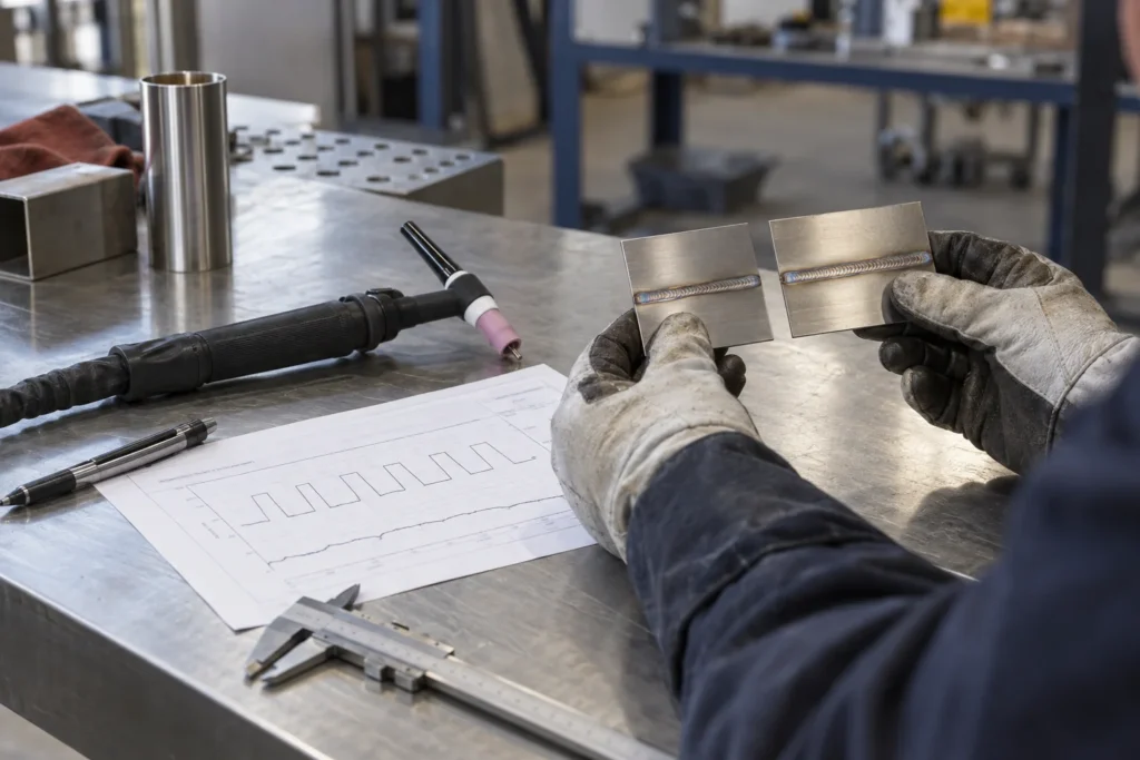
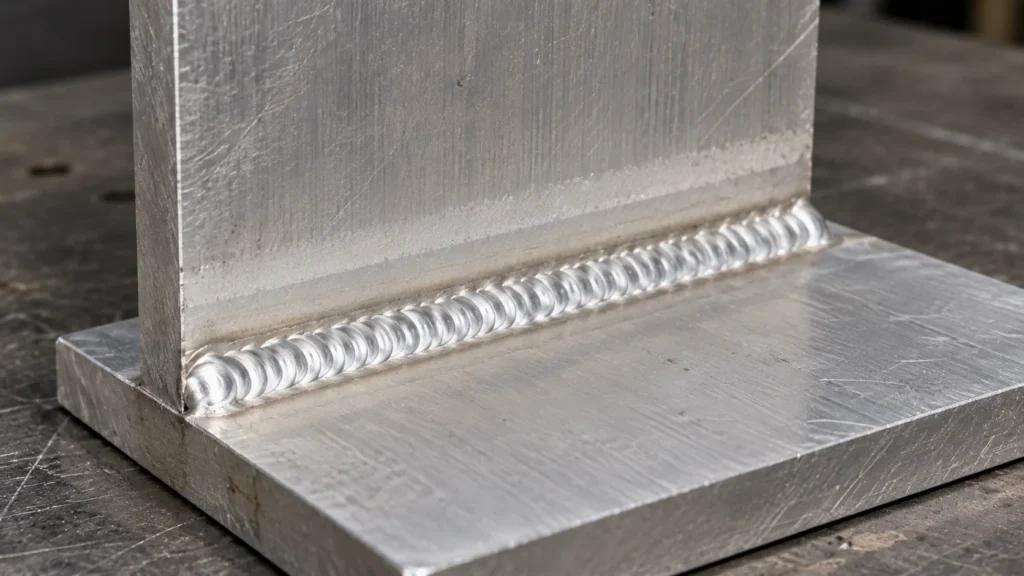
TIG Pulse Settings: Peak, Background and Frequency Guide
Introduction
Reliable TIG pulse settings start with a clear description of what each control changes. Peak current, background current, peak time and pulse frequency describe different parts of the current cycle. Copying four display numbers from another machine can produce a different result if its percentages, remote-control behaviour or operating mode are defined differently.
For fabrication plants, industrial OEMs and welding-equipment buyers, the useful output is a documented trial that another operator can repeat. This guide explains the controls, separates pulse timing from AC polarity control, and provides a practical setup-record framework. It focuses on conventional two-level pulsed TIG. It does not supply a qualified welding procedure or universal settings for every alloy, joint and machine. Confirm the exact equipment manual and the applicable procedure with the responsible welding engineer.
What Do TIG Pulse Settings Control?
Pulsed TIG welding varies current between a higher peak level and a lower background level. The pulse controls determine those levels and how the cycle is divided in time. Shielding, filler selection, joint preparation and travel speed remain separate parts of the welding procedure.
Begin with the welding task
State the problem before adjusting the panel. A thin stainless assembly might need better control of distortion. Another job might require a repeatable filler-addition rhythm or consistent operation around a changing joint position. Define the observation that would demonstrate improvement. A decorative ripple pattern alone cannot demonstrate fusion, corrosion suitability or compliance with an acceptance standard.
Miller's explanation of TIG pulse controls describes the basic peak/background principle. The trial and purchasing records below extend that concept into a shop handover method. Their blank fields are a proposed framework, not records of GWELD production results.
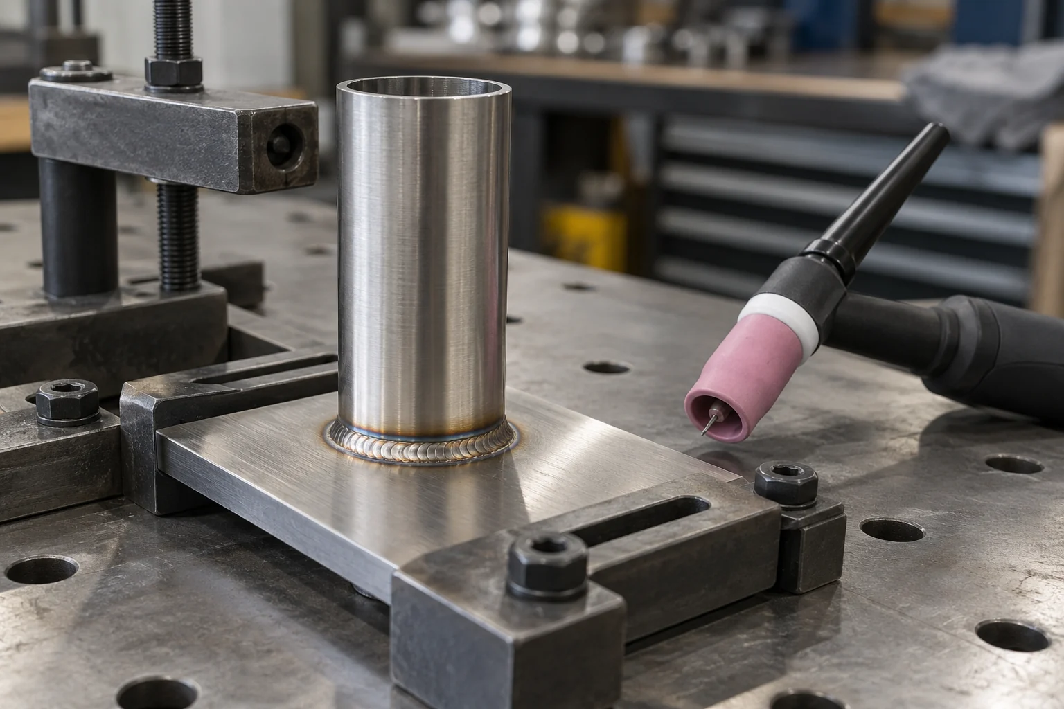
AI-generated illustrative trial setup; not a photograph of a GWELD factory test or an accepted production weld.
Translate the Four Pulse Controls Before Testing
Build a control dictionary for the exact model and mode. Similar panel labels can represent different quantities. Record the displayed unit and the manual's definition together.
| Control | Meaning and setup check |
|---|---|
| Peak current | Higher current level in the pulse cycle. Confirm whether the panel sets an actual level or a limit affected by a remote control. |
| Background current | Lower current level. Check whether it is entered in amps or as a percentage of peak current. |
| Peak time | Share of one pulse cycle spent at peak. Confirm whether the displayed percentage refers to peak time or background time. |
| Pulse frequency | Number of pulse cycles per second, commonly shown as PPS or Hz. Check mode-specific limits and linked controls. |
Keep current percentages separate from time percentages
A background value of 30% describes a current relationship when the manual defines it that way. A peak-time value of 30% describes a time relationship. Those two percentages are not interchangeable. Write their full names in the setup record instead of recording an unexplained pair of numbers.
The Lincoln Aspect 230 operator's manual, Pulse Sequencer Functions provides an example of these definitions. Its available ranges and coupled settings belong to that model. A GWELD quotation should identify the corresponding controls on the proposed machine.
Separate Pulse Frequency from AC Frequency and Duty Cycle
TIG pulse frequency counts the repetition of the peak/background cycle. AC frequency concerns the repetition of the alternating-polarity waveform. AC balance concerns the polarity time distribution. A machine offering several frequency controls needs an explicit description of each one.
Check the operating mode
For a DC pulse trial, record the selected polarity and pulse controls. For an AC pulse trial, also record AC frequency, balance convention and any waveform options. The manufacturer may limit or link pulse adjustments in AC mode. Ask for the actual mode-specific manual rather than assuming that a brochure's maximum frequency applies to every process.
Our AC balance setup and QC guide covers EN/EP interpretation. Keep those settings in separate record fields.
Two meanings of duty cycle
Pulse duty cycle can mean the fraction of a pulse spent at peak current. The power source's rated duty cycle describes a thermal operating limit under stated test conditions. A 50% pulse-time setting does not establish a 50% machine rating or permission to exceed the torch's rating. Verify equipment and cooling limits independently.
Read One Pulse Cycle Before Copying a Recipe
A simple timing calculation helps expose recording mistakes. For an ideal rectangular two-level waveform, cycle time in seconds equals 1 divided by frequency in Hz. Peak duration equals cycle time multiplied by the peak-time fraction. Background occupies the remainder.
A timing example, not a recommended setting
Assume 2 pulses per second and 40% peak time. One cycle lasts 0.5 seconds. The peak portion lasts 0.2 seconds and the background portion lasts 0.3 seconds. At 4 pulses per second with the same 40% fraction, those durations become 0.1 and 0.15 seconds. The proportion of total time at peak remains 40% in this ideal model.
Changing frequency alone therefore does not automatically increase the peak-time fraction. Real equipment can use shaped transitions or linked controls. Check its documented behaviour before applying the calculation. For manual welding, record how the operator coordinates filler and movement with the selected cycle; another operator may use a different technique even with identical display values.
Run a Controlled Pulse Trial for Stainless Steel
A useful pulsed TIG welding stainless steel trial keeps the joint and inspection plan stable while the engineer evaluates a defined change. Prepare representative coupons with traceable identifiers before moving to production parts.
Fix the conditions that can hide the effect
Record material grade and thickness, joint fit-up, preparation, fixture, welding position, filler classification, tungsten preparation, torch parts and shielding arrangement. Define interpass or starting-temperature controls where the procedure requires them. Use the same inspection method for the baseline and subsequent trials.
Use the stainless steel TIG process guide for the surrounding material and purging discussion. Pulse control cannot compensate for an unsuitable shielding arrangement or contaminated preparation.
Make the trial sequence auditable
-
- Document the approved baseline, including whether pulse is enabled and how the controls are defined.
- Select one control to evaluate within the procedure and equipment limits.
- Identify the coupon before welding and record the actual display values.
- Keep travel method and the agreed preparation controls consistent.
- Inspect using the defined criteria and record both acceptable and unacceptable observations.
- Repeat the candidate condition before deciding whether to transfer it to production.
If the trial changes current, timing and travel speed together, record it as a combined change. It can still be useful, but it cannot isolate which variable caused the observed difference. A failed coupon also provides evidence when its conditions are known.
Stop a trial if the arc behaviour, equipment condition or operator discomfort raises a safety concern. Follow the site risk assessment, required PPE, ventilation and the manufacturer's instructions. Qualified personnel should handle equipment faults and service work.
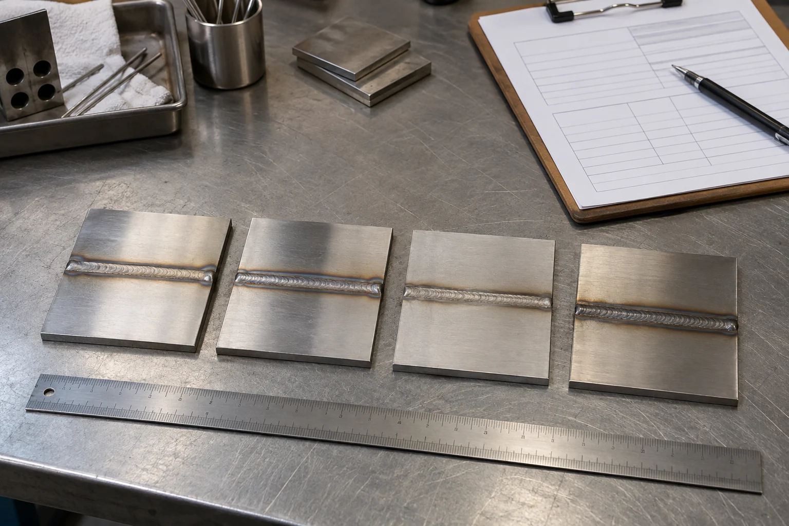
AI-generated QC illustration; coupon appearance and props do not represent measured performance or certification.
Troubleshoot One Variable at a Time
Use symptoms to choose an inspection path rather than a universal corrective number. The same visible result can have several causes.
| Observation | What to verify before changing the pulse program |
|---|---|
| Inconsistent fusion or bead width | Joint fit-up, arc length, travel method, actual current definition and the inspection result. |
| Puddle control becomes difficult between peaks | Background-current definition, operator timing and whether the selected mode behaves as expected. |
| Distortion varies between coupons | Fixture, starting temperature, sequence and travel speed as well as the pulse values. |
| Discoloration, porosity or tungsten changes | Shielding, cleanliness, gas path and electrode condition; avoid treating every defect as a frequency problem. |
| Settings differ after recall or reconnection | Saved program, remote-control mode, linked controls and the model-specific recall procedure. |
Use a return-to-baseline check
If a trial result changes unexpectedly, return to the documented baseline on a fresh comparable coupon when safe and permitted. A baseline that no longer reproduces its earlier result points to an uncontrolled condition. Investigate that condition before attributing the difference to pulse frequency.
For defects involving the electrode, use the TIG tungsten contamination checklist. Keep the defect record linked to the trial ID.
Why Average Current Does Not Prove Heat Input
For an ideal rectangular two-level DC waveform, a time-weighted average is Iavg = Ipeak * D + Ibackground * (1 - D), where D is the peak-time fraction. This is a current calculation. It is not a direct measurement of weld heat input, penetration or power-source thermal loading.
Check the arithmetic and its limits
As a hypothetical example, choose a peak of 120 A, background of 30% of peak, and 40% peak time. Background current is 36 A. The ideal average is 120 * 0.40 + 36 * 0.60 = 69.6 A. These numbers demonstrate the calculation only; they are not recommended parameters for a particular thickness or joint.
Under that ideal model, frequency does not appear in the average-current equation when both levels and their time fractions stay fixed. Actual waveform shape and equipment coupling still matter. Electrical energy also depends on voltage over time; energy per unit weld length depends on travel. A claimed percentage reduction in heat input requires suitable measurements and a defined comparison.
Do not substitute this average for an RMS-current assessment, a measured waveform or the manufacturer's rated duty-cycle conditions. Use the quantity required by the engineering question and the applicable procedure.
Build a Reusable TIG Pulse Setup Record
A TIG pulse settings chart is useful when it preserves definitions and traceability. A chart containing only thickness and amperage leaves too many conditions unstated for production transfer.
Keep these fields with every approved trial
-
- Record number, revision, date, approver and linked procedure.
- Power-source model, relevant firmware identification and operating mode.
- Peak current, background current, background units, peak-time convention and pulse frequency.
- AC frequency, balance convention and waveform selection when applicable.
- Material, thickness, joint, position, filler and tungsten preparation.
- Torch, cooling, shielding, fixture and travel-method details.
- Starting and finishing sequence, remote-control configuration and saved program reference.
- Coupon IDs, inspection criteria, results and conditions requiring a new trial.
Attach a photograph of the selected control screens when permitted. It supplements the written definitions; it cannot replace them. Keep rejected trial revisions distinguishable from the approved version so an operator cannot recall the wrong program by a similar name.
Decide what triggers revalidation
Changes in machine model, control definition, material, fixture or inspection requirement may justify another trial. Let the responsible engineer define the boundary. A stored memory number has meaning only on the identified machine and configuration.
Check Remote Control and Start-to-Stop Behaviour
A foot pedal, torch control or automated interface can change how panel settings relate to delivered current. Confirm the supported input, selected mode and interpretation of the peak setting from the exact manual. Do not infer compatibility from a connector's appearance.
Test the whole sequence
Ask the supplier to demonstrate the agreed sequence with the actual accessories. Observe start, welding, termination, power cycling and program recall as applicable. Identify which controls are stored and which depend on the connected remote. Separate operator observations from instrumented measurements in the acceptance record.
Pre-flow, slope and post-flow are separate sequence parameters. The TIG pre-flow and post-flow setup guide provides a separate gas-timing record. Preserve the approved gas sequence while testing pulse controls unless the engineer intentionally changes both.
For automated cells, request an interface specification and acceptance demonstration. Industrial-network support, parameter backup and fault reporting are model-specific requirements to verify, not capabilities implied by the word digital.
Compare Supplier Evidence Before Ordering
A purchasing specification should connect the proposed power source to the approved application and its repeatability requirements. Maximum advertised pulse frequency is only one field in that specification.
Ask for the relevant deliverables
Request the exact model manual, a control-definition sheet, the supported ranges in the required mode, and a sample trial using representative joints. Specify what must be recorded and who approves the inspection. For a fleet, include the method for transferring settings between units and training another shift.
-
- Confirm the required supply, output range and rated operating conditions.
- Match the torch, cooling and remote accessories to the proposed work.
- Identify available parameter storage and any mode-dependent restrictions.
- Agree on documentation, spare parts, service contacts and acceptance responsibilities.
The pulse TIG manufacturer sourcing guide covers broader OEM evaluation. Use the control record here as a technical appendix to that commercial discussion.
Review the GWELD TIG welder range and ask which configuration matches the intended trial. Certifications, component sourcing, duty-cycle claims and interface capabilities require evidence for the quoted model. This guide does not establish them.
Related Products

TIG 180/200/225 DC Pulse
A compact, air-cooled TIG/Stick inverter welder designed for AC and DC welding.
- Built with durable internal components and a reinforced structure for long-term reliability.
- Supports TIG Pulse and Stick welding across stainless steel, carbon steel, copper, and other common metals.
- Compact and portable design for workshops, garages, mobile repair, and everyday fabrication work.

TIG 300/400/500 DC Pulse
A compact, air-cooled TIG/Stick inverter welder designed for AC and DC welding.
- Uses stronger and more durable material
- Water Cooler compatible.
- Equipped with selected and reliable accessories to enhance the welder’s experience.
- Industrial level welder with a higher redundancy design increases reliability, extends service life, and enhances durability.
TIG 180/200/225P ACDC
A compact, air-cooled TIG/Stick inverter welder designed for AC and DC welding.
- Designed for aluminum welding, with precise control for thin and delicate materials.
- Advanced pulse technology helps reduce heat input and improve weld appearance.
- Built with durable components and a rugged structure for long-term reliability.
Related Solutions

General Fabrication
The ultimate TIG welder solution for diverse fabrication needs. Built with solid materials and thoughtful R&D, our machines offer the precise control required for stainless steel and the reliable power for carbon steel. Experience professional performance in a balanced design engineered for the versatile fabricator.

Automotive
From thin-gauge body panels to heavy-duty chassis components, GWELL provides the precise arc control and reliable performance required for the modern automotive industry. Our Pro-tier technology ensures every joint meets the highest safety and aesthetic standards.

Maintenance & Repair
The ultimate TIG welder solution for unpredictable repair demands. Built with solid materials and thoughtful R&D, our machines provide the precise arc control needed for delicate stainless repairs and the reliable power for rugged on-site fixes. Experience professional performance in a balanced design that is compact, portable, and engineered to keep your operations ready to go—no matter the location.
Frequently Asked Questions
Conclusion
Document TIG pulse settings with their units, definitions and operating mode before transferring them into production. Peak and background current describe levels; peak time and frequency describe timing. AC controls, the equipment's thermal rating and the gas sequence need separate checks.
Use comparable coupons, a controlled trial and agreed inspection criteria to choose a repeatable setup. Keep the approved record with the machine and the relevant procedure. For a GWELD equipment proposal, send the material grade, thickness, joint, welding position, production pattern, supply and accessory requirements to the GWELD technical inquiry team. Request the exact control definitions and a matched trial plan with the quotation.