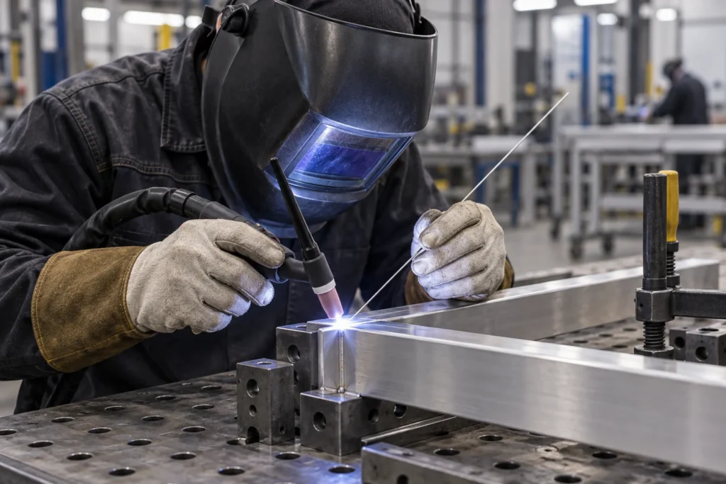
AC Balance TIG Welding: Aluminum Setup and QC Guide
Introduction
AC balance TIG welding controls how an alternating-current cycle is divided between electrode-negative and electrode-positive time. For an aluminum fabrication team, the important detail is what the machine's number actually means. A higher value can mean more electrode-negative time on one control, while another interface may describe electrode-positive time or a cleaning scale. Copying the number without its definition can change the process in the wrong direction.
This guide helps welding engineers, production supervisors and equipment buyers turn that control into a documented setup. It covers EN/EP interpretation, separation from frequency and pulse, representative trials, fault observations and shift handover. Use the exact model's operating manual and the applicable welding procedure to approve production settings. The examples below explain documentation and arithmetic; they are not a universal aluminum welding recipe.
What Does AC Balance Control in Aluminum TIG Welding?
AC balance changes the time allocation between the two polarities of an AC welding cycle. The electrode-positive portion contributes oxide-cleaning action, while electrode-negative time supports heating and fusion of the workpiece. The balance therefore affects the relationship between cleaning action and welding behavior, rather than simply making the machine more powerful.
Read the cleaning action in context
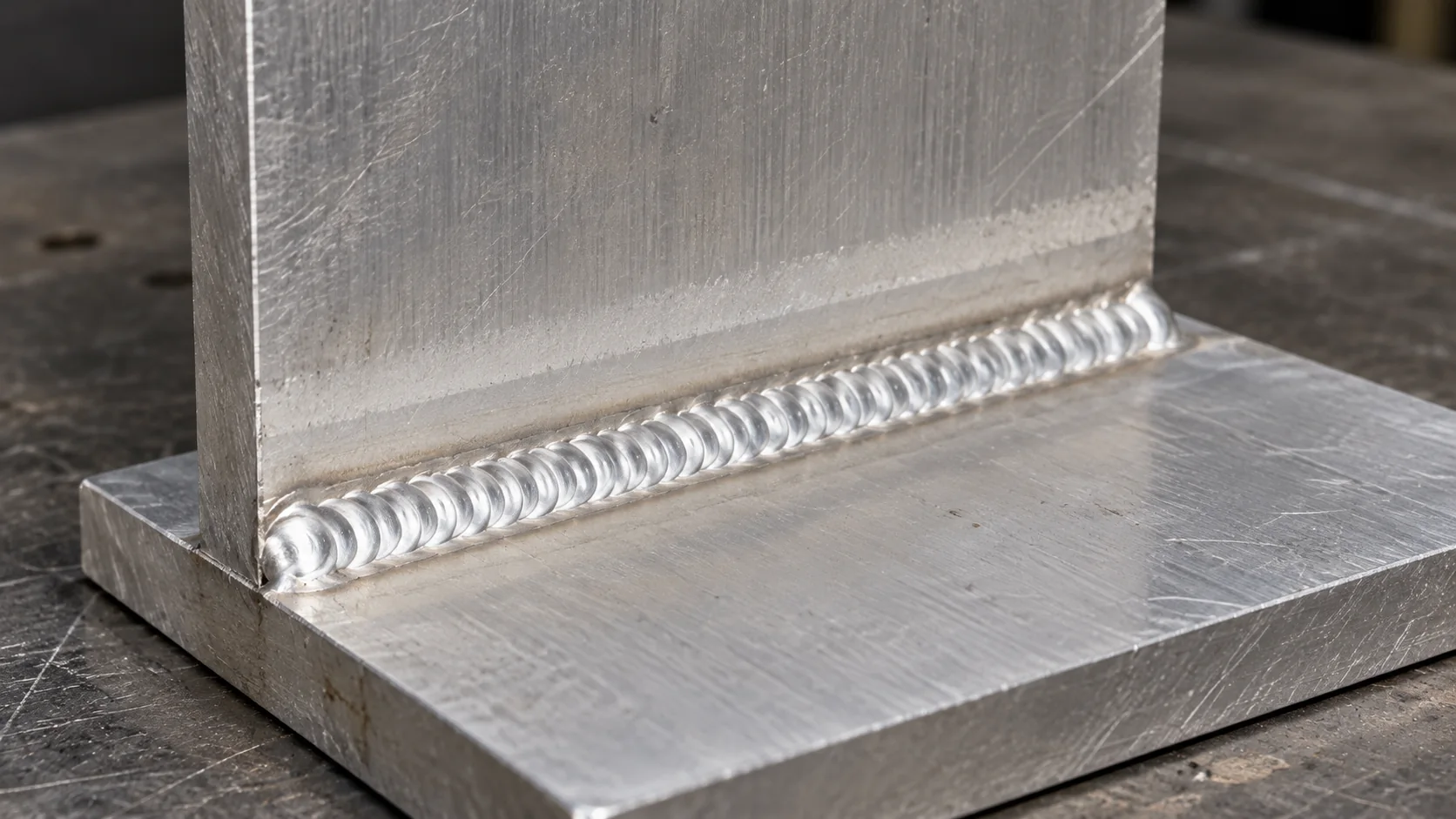
Miller's explanation of AC balance describes the role of both polarities and why surface preparation remains necessary. The pale etched area beside an aluminum weld can help document visible cleaning action, but its appearance alone does not release a weld for service. Apply the inspection criteria specified for the actual joint.
For a purchasing discussion, separate three questions: what the control changes, how its value is displayed, and how the resulting weld will be accepted. Keep photographs attached to sample identifiers. A visually attractive bead on an unidentified coupon gives the buyer little evidence about the alloy, preparation or procedure that produced it.
Read EN and EP Before Transferring a Setting
Translate a displayed balance value only after confirming its definition. Electrode negative is commonly shortened to EN; electrode positive is EP. Record the full label from the manual beside the number. A percent sign, by itself, does not identify the polarity or prove that the display represents a measured output.
A timing example, not a preset
If a documented control expresses the percentage of cycle time in EN, an illustrative setting of 70% EN leaves 30% EP. A separate machine displaying EP time would show 30% for that same timing split. This arithmetic does not mean the two machines produce identical welds. Current amplitudes, waveform, frequency and the rest of the setup still need to be matched or evaluated.
| Display definition | What increasing the value means |
|---|---|
| Percentage of EN time | More EN time and less EP time in the cycle. |
| Percentage of EP time | More EP time and less EN time in the cycle. |
| Cleaning scale or index | Use the model's manual; do not assume a percentage conversion. |
The Miller manual's percent-EN control example illustrates why the label matters. It is a reference for interpreting a named control, not a GWELD setting specification. When the definition is unclear, obtain written clarification before transferring a job between machines.
Separate AC Balance from Frequency, Pulse and Amperage
Balance, AC frequency, pulse and amperage describe different controls. Treat them as separate fields in the setup record. Otherwise, a trial that changes several controls at once cannot show which change caused a different result. A single saved program name is useful, but it should not replace a readable parameter record.
Keep the units attached
AC frequency describes welding cycles per second, whereas a timing-balance value describes the division of a cycle. Pulse controls describe modulation of welding current. On equipment with independent EN and EP current controls, timing and current amplitude are also distinct. Miller's waveform-control explanation provides context for these separate capabilities.
Write the control name, unit and selected operating mode together. An entry reading only 'frequency 100' is ambiguous if the machine has both AC-frequency and pulse-frequency menus. An entry reading only 'balance 70' is incomplete without the EN, EP or scale definition. Confirm which functions are available together on the quoted model.
For equipment-level selection, use the GWELD AC TIG welder buying guide. This article concentrates on the control record and the evidence needed to transfer it reliably into production.
Prepare Representative Aluminum Parts Before Tuning
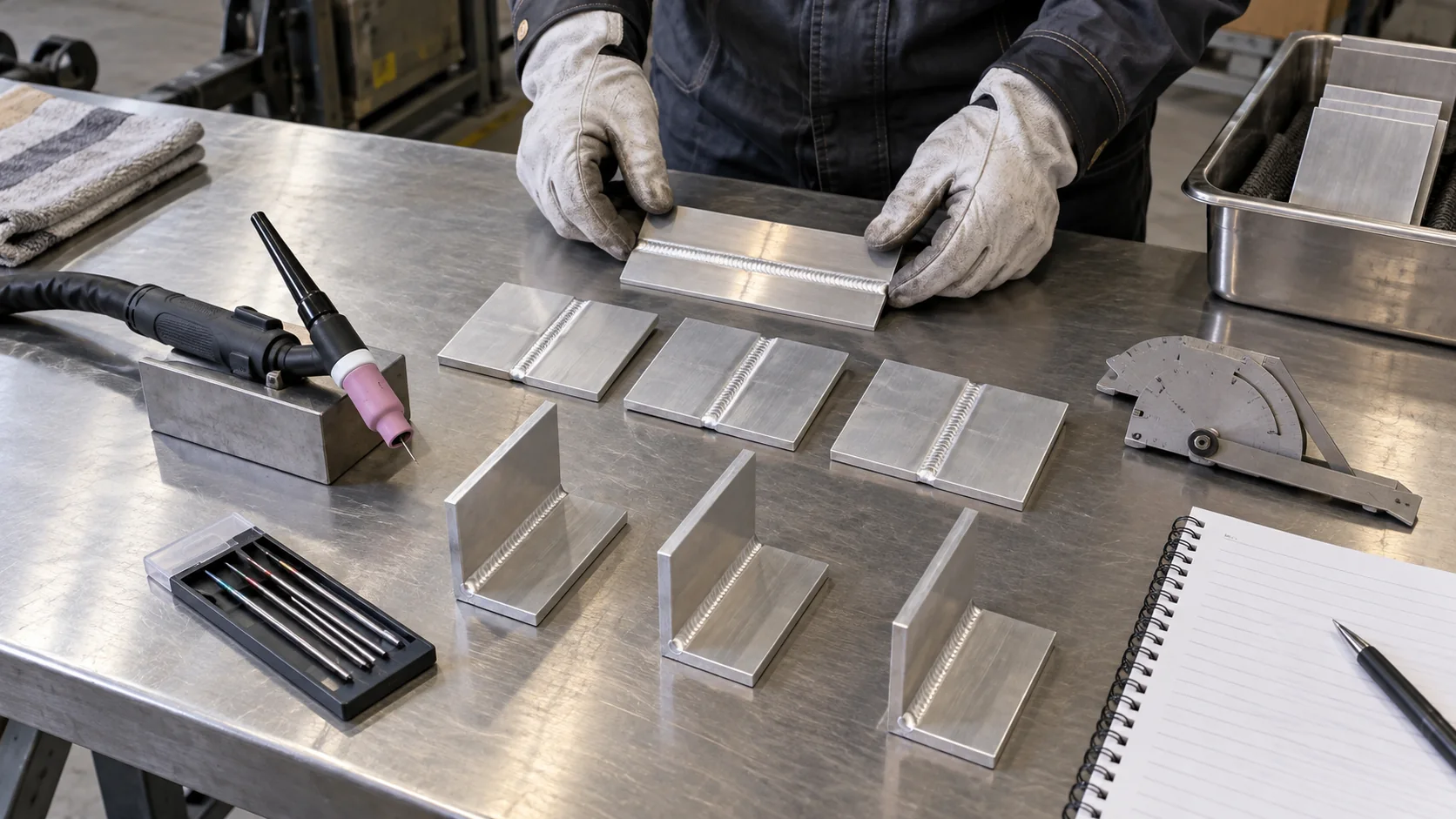
Use samples that represent the production material, surface condition and joint. Balance adjustment should follow a defined preparation process. If one coupon is freshly prepared and another has spent days in an uncontrolled storage area, their results cannot be attributed solely to a control change. Record the difference or repeat the comparison under equivalent conditions.
Write a sample identity that survives the trial
Give each coupon an identifier linked to alloy grade, thickness, joint geometry and preparation record. Include representative access constraints, starts and stops, and the intended welding position. Identify the filler classification and lot separately. The TIG welding wire selection guide supports the consumables discussion without replacing the project's filler approval.
Keep preparation tools and handling consistent with the approved shop practice. Follow the applicable safety instructions for any cleaning products. Do not place a recently treated part into welding until the specified preparation steps are complete. Ask the responsible welding engineer to define what conditions must be held constant and which variations the trial should intentionally include.
Include a difficult production feature
A flat demonstration coupon may be useful for initial comparison, but add a feature that matters to the order: an internal corner, restricted torch access or a repeated stop-start joint. Document why it was chosen. This gives procurement a connection between a supplier demonstration and the work that the machine will actually perform.
Run a Controlled AC Balance Trial
A useful trial changes a defined variable within the permitted procedure while recording the rest of the setup. Start from an approved baseline or a model-specific starting point supplied by the responsible welding specialist. Keep the reason for each change visible. The purpose is to select and document an acceptable process, not to produce the widest possible cleaning band.
A practical comparison sequence
- Confirm the machine model, AC mode, balance definition and applicable procedure.
- Prepare identified samples with the agreed material, filler and joint arrangement.
- Record the baseline settings, torch, tungsten, shielding and welding sequence.
- Make the baseline sample and retain its observations and inspection results.
- Change only the authorized balance variable, within the approved range, and identify the next sample.
- Compare the results against the predetermined criteria and record the selected condition.
Record elapsed welding time and any interruptions if repeatability over a production cycle is part of the evaluation. A short acceptable bead does not demonstrate continuous system capacity. If the trial reaches a thermal limit or requires an unplanned electrode change, keep that event in the log rather than omitting it from the supplier's final summary.
Use a defined decision point at the end: accepted for the specified job, further evaluation required, or rejected with a reason. A trial sheet that only lists the selected number leaves the next shift unable to judge whether the setting applies to a different material condition or joint.
Investigate Cleaning and Tungsten Symptoms Systematically
Treat a visible symptom as a reason to investigate the complete setup. A broad etched zone, a changing tungsten tip or an unstable arc is an observation, not a unique diagnosis. Preserve the sample and the settings before making changes. Use the operating manual and the responsible specialist's procedure to decide what to check next.
Separate observations from conclusions
Record the location and timing of the problem. Did the behavior occur at ignition, after a long run, at a joint transition or after the electrode touched the work? Photograph the tip before preparation changes, and identify whether the sample's surface condition differed from the baseline. The resulting record is more useful than a note saying 'bad balance.'
| Observation | What to record and investigate |
|---|---|
| Cleaning band changes | Display definition, preparation, selected balance and incoming surface condition. |
| Tungsten appearance changes | Electrode identity, contact events, current settings, shielding and run duration. |
| Arc or bead behavior changes | Joint location, travel sequence, torch arrangement and all changed controls. |
| Result varies between shifts | Program revision, operator handover, materials and preparation records. |
For electrode-specific checks, follow the TIG tungsten contamination troubleshooting guide. For shielding-related observations, review the TIG shielding gas and flow guide. Keeping these checks separate prevents the balance control from becoming an explanation for every welding defect.
Escalate results that do not meet the project's acceptance requirements. Repeated tuning without a recorded hypothesis can consume samples while concealing the original cause. Identify the responsible person and the disposition before restarting production.
Create an AC Balance Setup and Change Log
A reusable log connects a machine setting with a specific job and accepted sample. Keep the raw display value and its meaning in separate fields. This makes the record readable when a different machine, operator or service technician revisits it. The log proposed here is a planning template, not a GWELD test result.
Minimum fields for a traceable record
- Job, drawing revision, material grade, thickness and sample identifier.
- Machine model, serial identifier, manual revision and operating mode.
- Balance display value, EN/EP or scale definition, and the source of that definition.
- Other control names, values and units, including any independent polarity-current controls.
- Torch, tungsten, filler and shielding configuration.
- Preparation method, operator, welding sequence and interruptions.
- Inspection method, results, deviations and release authority.
For each change, add the previous value, new value, reason, sample reference and decision. Use the same vocabulary on the traveler, program list and training sheet. If the machine provides saved programs, link the program identifier to the controlled record; confirm that the program really contains the intended parameters before relying on recall.
Keep comparisons honest
Do not label a change as an improvement unless the comparison supports it. A shorter trial may be unsuitable for estimating electrode replacement or long-run behavior. Record unmeasured items explicitly. When a supplier changes the fixture, filler or waveform during a demonstration, create a separate comparison rather than merging the result into the original balance-only trial.
Transfer the Approved Setup Across Shifts and Machines
Production handover should transfer the job conditions and approved record, not just the balance number. Before a new shift starts, confirm the program revision, operating mode, consumables and sample reference. Give the operator a clear route for reporting a different incoming condition or an unexpected result.
Train the direction of adjustment
Have the operator explain what increasing the displayed value means on that exact model. Use the manual's terminology and a timing illustration if appropriate. This short check exposes an EN/EP misunderstanding before it becomes an undocumented production change. Include where to find the approved range and who may authorize a deviation.
When transferring a job to another machine, compare the available controls and their definitions first. Identify functions that are absent, expressed differently or combined in a preset. Translate only what is defined, then evaluate the complete replacement setup under the required procedure. A shared product-family name does not prove equivalent controls or identical saved-program behavior.
Preserve the selected condition
After maintenance or a software change, check the setup against the controlled record before releasing the machine. Confirm any reset behavior through the model's documentation. Keep a dated record of the verification and its sample reference. These checks make the approved baseline recoverable when production later needs to investigate a variation.
Specify AC Controls When Buying an Aluminum TIG System
An equipment specification should ask the supplier to identify the available control functions and the evidence needed for acceptance. Avoid a requirement that merely says 'adjustable AC balance.' State which jobs the system must support, how settings will be documented and what the buyer expects to verify during the trial.
Ask for model-specific answers
- What does the balance display represent, and what is its adjustment range and resolution?
- Which AC waveform, frequency and current controls are available in the selected mode?
- Which settings can be saved, recalled or backed up, and what are the limitations?
- Which torch, electrode arrangement and cooling package are proposed for the workload?
- What documentation, training and service support accompany the exact configuration?
GWELD's TIG 180/200/225P ACDC product family is one starting point for an aluminum welding equipment discussion. Confirm the selected model's controls and rated conditions in the quotation and operating documentation. Do not infer every function or rating from a family name or a general website description.
Include installation details and the intended production cycle. A balance-control demonstration does not establish torch capacity, cooling suitability or usable output over a shift. For the broader production approach, read the industrial aluminum TIG welding guide and align the equipment proposal with the complete application.
Use the Trial Record to Compare Supplier Proposals
Compare suppliers against the same application and acceptance plan. Each proposal should identify the machine, accessories, documented controls and trial scope. Ask what is included and what remains the buyer's responsibility. This creates a clearer purchasing decision than comparing a maximum amperage figure with an unexplained balance percentage.
Close the documentation gaps before the order
Review whether the proposed manual matches the quoted model, whether the sample identifiers appear in the inspection record, and whether the final selected settings are recoverable. Ask the supplier to explain any difference between a demonstrated configuration and the shipped package. Resolve exclusions for remote controls, torches, cooling, consumables and training in writing.
An internal purchasing checklist can also record the date of clarification, document owner and unresolved item. Give each open item a decision rather than leaving a promising demonstration as its substitute. Where production qualification or customer approval is required, schedule that work separately from commercial acceptance of the equipment.
Prepare a useful GWELD inquiry
Send alloy grades, thickness range, joint drawings, inspection requirements, expected run pattern and destination electrical supply to the GWELD equipment consultation team. Add the AC control functions you need and the setup record you intend to use. Request a matched model, accessory package and defined sample evaluation. For OEM orders, include quantity, labeling, documentation and support requirements so the proposal can be reviewed as a complete package.
Related Products

TIG 180/200/225P ACDC
A compact, air-cooled TIG/Stick inverter welder designed for AC and DC welding.
- Designed for aluminum welding, with precise control for thin and delicate materials.
- Advanced pulse technology helps reduce heat input and improve weld appearance.
- Built with durable components and a rugged structure for long-term reliability.

TIG 315/350P ACDC
A compact, air-cooled TIG/Stick inverter welder designed for AC and DC welding.
- Water Cooler compatible.
- Uses stronger and more durable material.
- Equipped with selected and reliable accessories to enhance the welder’s experience.
- Industrial level welder with a higher redundancy design increases reliability, extends service life, and enhances durability.

TIG 400/500P ACDC
A compact, air-cooled TIG/Stick inverter welder designed for AC and DC welding.
- Water Cooler compatible.
- Uses stronger and more durable material.
- Equipped with selected and reliable accessories to enhance the welder’s experience.
- Industrial level welder with a higher redundancy design increases reliability, extends service life, and enhances durability.
Related Solutions

Automotive
From thin-gauge body panels to heavy-duty chassis components, GWELL provides the precise arc control and reliable performance required for the modern automotive industry. Our Pro-tier technology ensures every joint meets the highest safety and aesthetic standards.

General Fabrication
The ultimate TIG welder solution for diverse fabrication needs. Built with solid materials and thoughtful R&D, our machines offer the precise control required for stainless steel and the reliable power for carbon steel. Experience professional performance in a balanced design engineered for the versatile fabricator.

Heavy Fabrication
The ultimate TIG welder solution for heavy-duty industrial demands. Built with solid materials and thoughtful R&D, our machines offer the precise control required for high-integrity stainless steel joins and the reliable power needed for deep penetration in thick carbon steel. Experience professional performance in a balanced design engineered for the most demanding fabrication environments.
Frequently Asked Questions
Conclusion
AC balance TIG welding becomes easier to manage when the display definition, job conditions and accepted sample are recorded together. Confirm EN, EP or scale meaning; keep balance separate from other controls; prepare representative parts; and retain the reason and result of each authorized change. Carry the controlled record through shift handover and equipment replacement.
For an aluminum production or OEM purchasing project, request a GWELD AC TIG system proposal with your materials, joint drawings, workload and acceptance plan. A clearly defined trial and readable control record help engineering, quality and purchasing assess the same evidence.